TBCNT
EPWMxA
EPWMxB
TBPRD
(value)
CAZ P CB Z P CB CA Z P
Z P CA Z P CA Z PCBCB
Enhanced PWM (ePWM) Module
www.ti.com
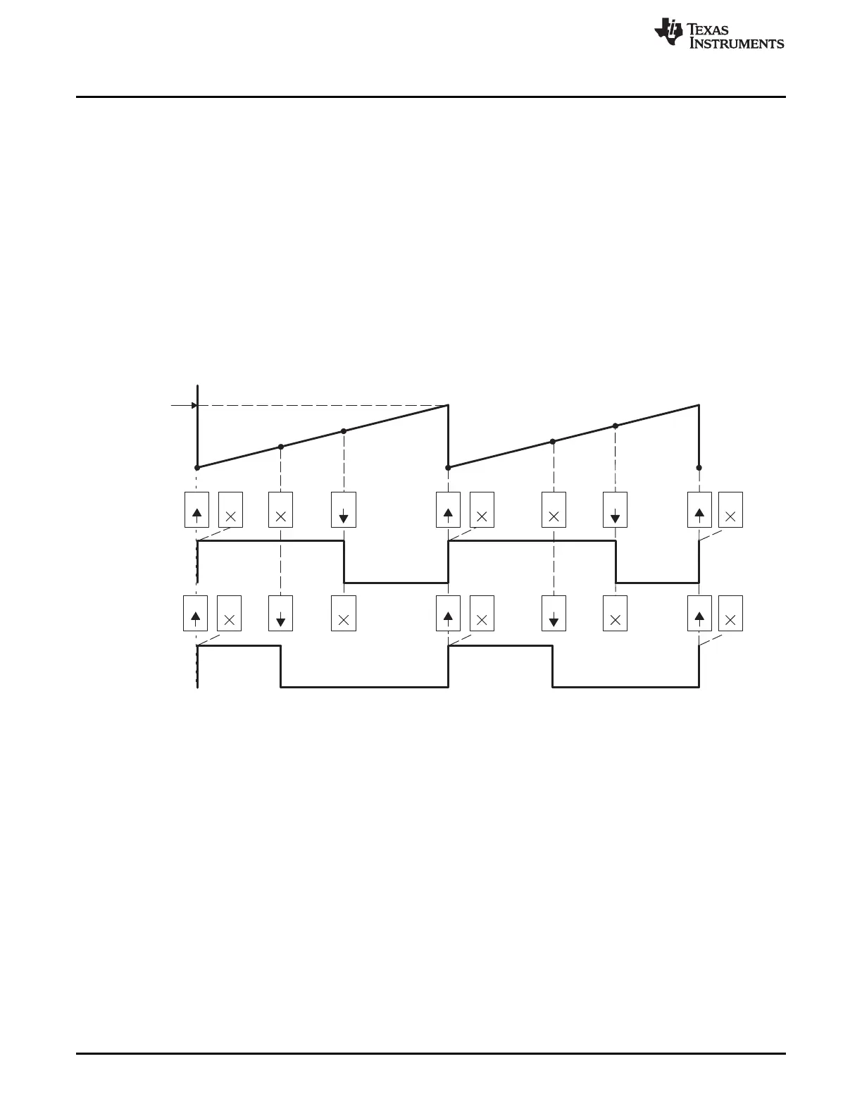
The PWM waveforms in Figure 15-27 through Figure 15-32 show some common action-qualifier
configurations. Some conventions used in the figures are as follows:
• TBPRD, CMPA, and CMPB refer to the value written in their respective registers. The active register,
not the shadow register, is used by the hardware.
• CMPx, refers to either CMPA or CMPB.
• EPWMxA and EPWMxB refer to the output signals from ePWMx
• Up-Down means Count-up-and-down mode, Up means up-count mode and Dwn means down-count
mode
• Sym = Symmetric, Asym = Asymmetric
Table 15-21 and Table 15-22 contains initialization and runtime register configurations for the waveforms
in Figure 15-27.
Figure 15-27. Up, Single Edge Asymmetric Waveform, With Independent Modulation on EPWMxA and
EPWMxB—Active High
(1) PWM period = (TBPRD + 1 ) × T
TBCLK
(2) Duty modulation for EPWMxA is set by CMPA, and is active high (that is, high time duty proportional to
CMPA).
(3) Duty modulation for EPWMxB is set by CMPB and is active high (that is, high time duty proportional to
CMPB).
(4) The "Do Nothing" actions ( X ) are shown for completeness, but will not be shown on subsequent diagrams.
(5) Actions at zero and period, although appearing to occur concurrently, are actually separated by one TBCLK
period. TBCNT wraps from period to 0000h.
1522
Pulse-Width Modulation Subsystem (PWMSS) SPRUH73H–October 2011–Revised April 2013
Submit Documentation Feedback
Copyright © 2011–2013, Texas Instruments Incorporated
 Loading...


