Z P Z P
TBCNT
EPWMxA
EPWMxB
CA CA
CB
CB
Enhanced PWM (ePWM) Module
www.ti.com
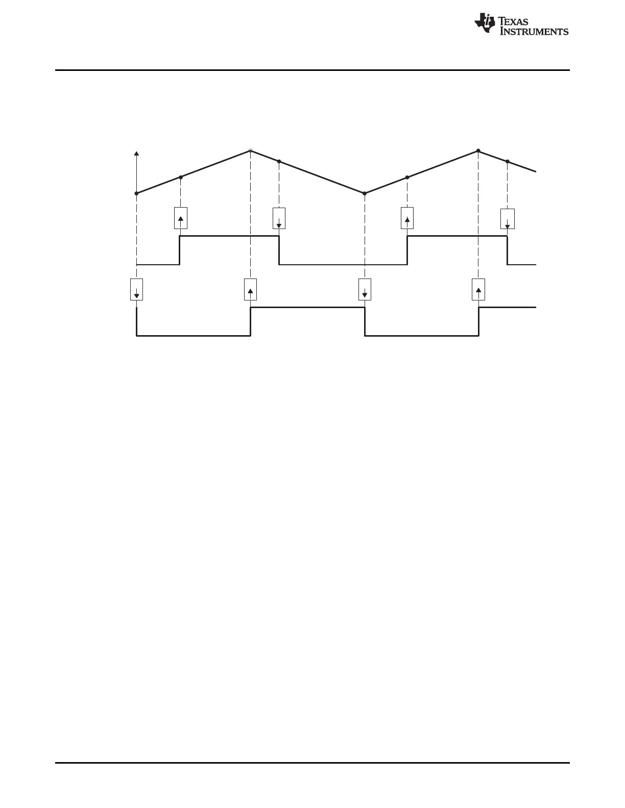
Table 15-31 and Table 15-32 contains initialization and runtime register configurations for the waveforms
in Figure 15-32. Use the code in Example 15-1 to define the headers.
Figure 15-32. Up-Down-Count, Dual Edge Asymmetric Waveform, With Independent Modulation on
EPWMxA—Active Low
(1) PWM period = 2 × TBPRD × TBCLK
(2) Rising edge and falling edge can be asymmetrically positioned within a PWM cycle. This allows for pulse
placement techniques.
(3) Duty modulation for EPWMxA is set by CMPA and CMPB.
(4) Low time duty for EPWMxA is proportional to (CMPA + CMPB).
(5) To change this example to active high, CMPA and CMPB actions need to be inverted (i.e., Set ! Clear and
Clear Set).
(6) Duty modulation for EPWMxB is fixed at 50% (utilizes spare action resources for EPWMxB)
1532
Pulse-Width Modulation Subsystem (PWMSS) SPRUH73H–October 2011–Revised April 2013
Submit Documentation Feedback
Copyright © 2011–2013, Texas Instruments Incorporated

 Loading...


