TBCNT
EPWMxA
EPWMxB
TBPRD
(value)
Z
T
Z
T
Z
T
CA CB CA CB
Enhanced PWM (ePWM) Module
www.ti.com
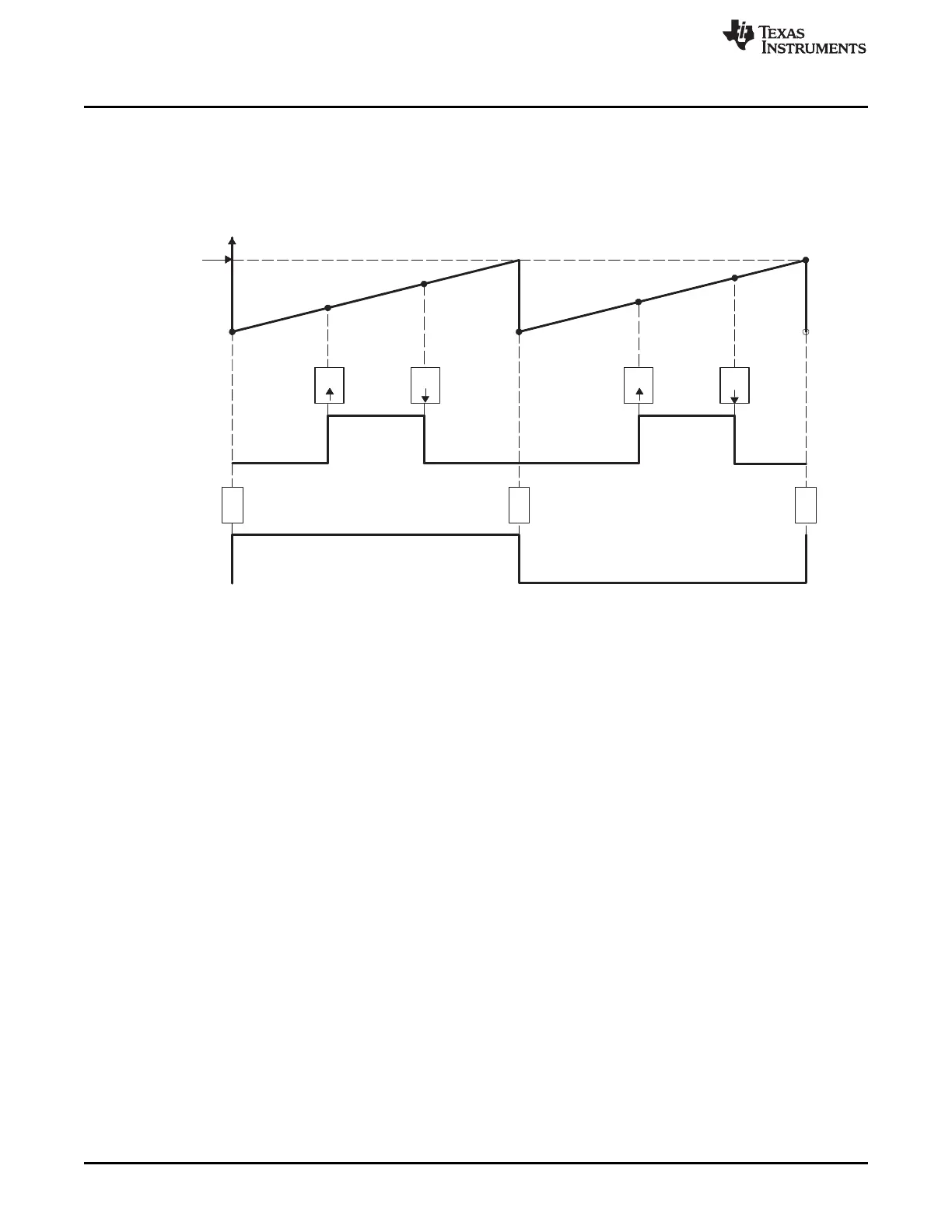
Table 15-25 and Table 15-26 contains initialization and runtime register configurations for the waveforms
Figure 15-29. Use the code in Example 15-1 to define the headers.
Figure 15-29. Up-Count, Pulse Placement Asymmetric Waveform With Independent Modulation on
EPWMxA
(1) PWM frequency = 1/( (TBPRD + 1 ) × T
TBCLK
)
(2) Pulse can be placed anywhere within the PWM cycle (0000h - TBPRD)
(3) High time duty proportional to (CMPB - CMPA)
(4) EPWMxB can be used to generate a 50% duty square wave with frequency = 1/2 × ((TBPRD + 1) × TBCLK)
1526
Pulse-Width Modulation Subsystem (PWMSS) SPRUH73H–October 2011–Revised April 2013
Submit Documentation Feedback
Copyright © 2011–2013, Texas Instruments Incorporated
 Loading...


