P U
size1
Protected data Unused data
bch_blk_ptr inactive
0
Mode
Size 0 Size 1
P
U
Manual mode
to ECC divider
M0
unused
Rd/Wr/
SW
size 0
www.ti.com
GPMC
There are cases where the same NAND access contains both data and the ECC protecting that data. This
is the case when the data/ECC boundary (which can be on any nibble) does not coincide with an access
boundary. The ECC is calculated on-the-fly following the write. In that case, the write must also contain
part of the ECC because it is impossible to insert the ECC on-the-fly. Instead:
• During the initial page write (BCH encoding), the ECC is replaced by dummy bits. The BCH encoder is
by definition turned OFF during the ECC section, so the BCH result is unmodified.
• During a second phase, the ECC is written to the correct location, next to the actual data.
• The completed line buffer is then written to the NAND array.
7.1.3.3.12.3.2.5 Wrapping Modes
For a given wrapping mode, the module automatically goes through a specific number of sections, as data
is being fed into the module. For each section, the BCH core can be enabled (in which case the data is
fed to the BCH divider) or not (in which case the BCH simply counts to the end of the section). When
enabled, the data is added to the ongoing calculation for a given sector number (for example, number 0).
Wrapping modes are described below. To get a better understanding and see the real-life read and write
sequences implemented with each mode, see Section 7.1.3.3.12.3.3.
For each mode:
• A sequence describes the mode in pseudo-language, with for each section the size and the buffer
used for ECC processing (if ON). The programmable lengths are size, size0 and size1.
• A checksum condition is given. If the checksum condition is not respected for a given mode, the
modules behavior is unpredictable. S is the number of sectors in the page; size0 and size1 are the
section sizes programmed for the mode, in nibbles.
Note that wrapping modes 8, 9, 10, and 11 insert a 1-nibble padding where the BCH processing is OFF.
This is intended for t = 4 ECC, where ECC is 6 bytes long and the ECC area is expected to include (at
least) 1 unused nibble to remain byte-aligned.
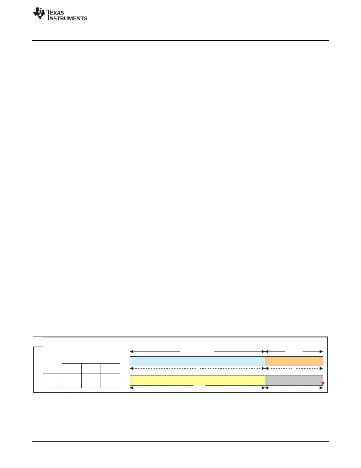
7.1.3.3.12.3.2.6 Manual Mode (0x0)
This mode is intended for short sequences, added manually to a given buffer through the software data
port input. A complete page may be built out of several such sequences.
To process an arbitrary sequence of 4-bit nibbles, accesses to the software data port shall be made,
containing the appropriate data. If the sequence end does not coincide with an access boundary (for
example, to process 5 nibbles = 20 bits in 16-bit access mode) and those nibbles need to be skipped, a
number of unused nibbles shall be programmed in size1 (in the same example: 5 nibbles to process + 3 to
discard = 8 nibbles = exactly 2 x 16-bit accesses: we must program size0 = 5, size1 = 3).
Figure 7-37 shows the manual mode sequence and mapping. In this figure, size and size0 are the same
parameter.
Figure 7-37. Manual Mode Sequence and Mapping
319
SPRUH73H–October 2011–Revised April 2013 Memory Subsystem
Submit Documentation Feedback
Copyright © 2011–2013, Texas Instruments Incorporated
 Loading...


