size1
size1 size1
size1
inactive
P P E E512 bytes 512 bytes 1 1
1 1
U U E E512 bytes 512 bytes
U U E E512 bytes 512 bytes
P P E E512 bytes 512 bytes
1 1
size1 size1
10 i.
Ecc0 Ecc1Pad Pad
size1size1size0 size0
size1size1size0 size0
size1size1size0
Data0 Data1 Ecc0 Ecc1
non-ECC spares
0 1
0 1 1
inactive
0
Write
Read
6
5
P E
P E
Mode Size0 Size1
Per-sector spares, separate ECC
Spares covered by sector ECC.
All ECC at the end.
Prot0 Prot1
10
10
ECC
Data0 Data1 Ecc0 Ecc1
non-ECC spares
0 1 10Read 4 SU E
Mode Size0 Size1
Per-sector spares, separate ECC
Spares not covered by ECC.
All ECC at the end.
ECC
Unprot0 Unprot1
inactive
size1size1size0 size0
size0 size0
Data0 Data1
non-ECC spares
0 1
0 1
inactiveWrite
Read
6
11
P 1+E
P E
Mode Size0 Size1
Per-sector spares, separate ECC
Spares covered by sector ECC.
All ECC at the end, left-padded.
Prot0 Prot1
10
10
ECC
size0
Data0 Data1
Sector data non-ECC spares
0 1Read 9 SU E
Mode Size0 Size1
Per-sector spares, separate ECC
Spares not covered by ECC.
All ECC at the end, left-padded.
ECC
Unprot0 Unprot1
inactive
Ecc0 Ecc1Pad Pad
1 1size1 size1
10 i.i.
Sector data
Sector data Sector data
Sector data Sector data
Sector data Sector data
M9
M
10
M
11
M
12
0 1 inactiveWrite 6 0 U+1+E
0 1Write 6 0 U+E
GPMC
www.ti.com
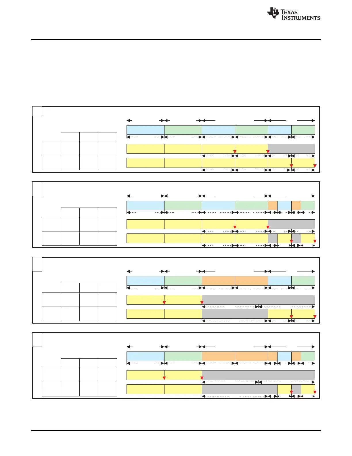
7.1.3.3.12.3.3.3 Per-Sector Spare Mapping, With ECC Separated at the End of the Page
In these schemes (Figure 7-40), each 512-byte sector of the main area is associated with two sections of
the spare area.
• ECC section, all aligned at the end of the page
• other data section, aligned before the ECCs, each of which may or may not be protected by its sectors
ECC
Figure 7-40. NAND Page Mapping and ECC: Per-Sector Schemes, with Separate ECC
326
Memory Subsystem SPRUH73H–October 2011–Revised April 2013
Submit Documentation Feedback
Copyright © 2011–2013, Texas Instruments Incorporated
 Loading...


