Multimedia Card Registers
www.ti.com
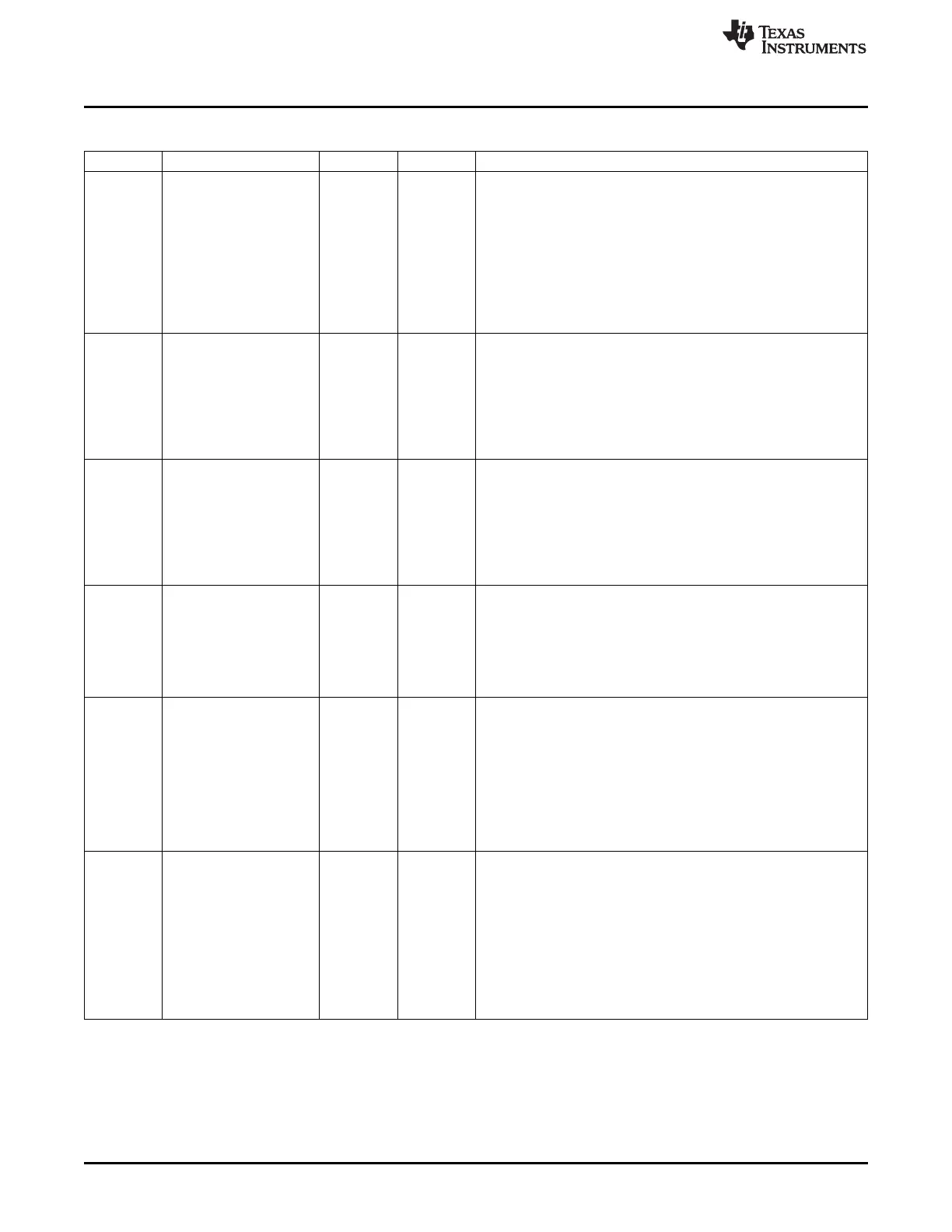
Table 18-24. SD_CON Register Field Descriptions (continued)
Bit Field Type Reset Description
10-9 DVAL R/W 0h Debounce filter value (all cards).
This register is used to define a debounce period to filter the card
detect input signal (SDCD).
The usage of the card detect input signal (SDCD) is optional and
depends on the system integration and the type of the connector
housing that accommodates the card.
0x0 = 33 us debounce period
0x1 = 231 us debounce period
0x2 = 1 ms debounce period
0x3 = 8.4 ms debounce period
8 WPP R/W 0h Write protect polarity (SD and SDIO cards only).
This bit selects the active level of the write protect input signal
(SDWP).
The usage of the write protect input signal (SDWP) is optional and
depends on the system integration and the type of the connector
housing that accommodates the card.
0x0 = Active high level
0x1 = Active low level
7 CDP R/W 0h Card detect polarity (all cards).
This bit selects the active level of the write protect input signal
(SDWP).
The usage of the write protect input signal (SDWP) is optional and
depends on the system integration and the type of the connector
housing that accommodates the card.
0x0 = Active high level
0x1 = Active low level
6 MIT R/W 0h MMC interrupt command (MMC cards only).
This bit must be set to 1, when the next write access to the
command register (SD_CMD) is for writing a MMC interrupt
command (CMD40) requiring the command timeout detection to be
disabled for the command response.
0x0 = Command timeout enabled.
0x1 = Command timeout disabled.
5 DW8 R/W 0h 8-bit mode MMC select (MMC cards only).
For SD/SDIO cards, this bit must be cleared to 0.
For MMC card, this bit must be set following a valid SWITCH
command (CMD6) with the correct value and extend CSD index
written in the argument.
Prior to this command, the MMC card configuration register (CSD
and EXT_CSD) must be verified for compliancy with MMC standard
specification.
0x0 = 1-bit or 4-bit data width
0x1 = 8-bit data width
4 MODE R/W 0h Mode select (all cards).
This bit selects the functional mode.
0x0 = Functional mode. Transfers to the MMC/SD/SDIO cards follow
the card protocol. The MMC clock is enabled. MMC/SD transfers are
operated under the control of the SD_CMD register.
0x1 = SYSTEST mode. SYSTEST mode. The signal pins are
configured as general-purpose input/output and the 1024-byte buffer
is configured as a stack memory accessible only by the local host or
system DMA. The pins retain their default type (input, output or in-
out). SYSTEST mode is operated under the control of the SYSTEST
register.
3400
Multimedia Card (MMC) SPRUH73H–October 2011–Revised April 2013
Submit Documentation Feedback
Copyright © 2011–2013, Texas Instruments Incorporated

 Loading...


