A1 A0 B15 B14 B13 B12 B11 B10 B9 B8 B7 B6 B5 B4 B3 B2 B1 B0 C15
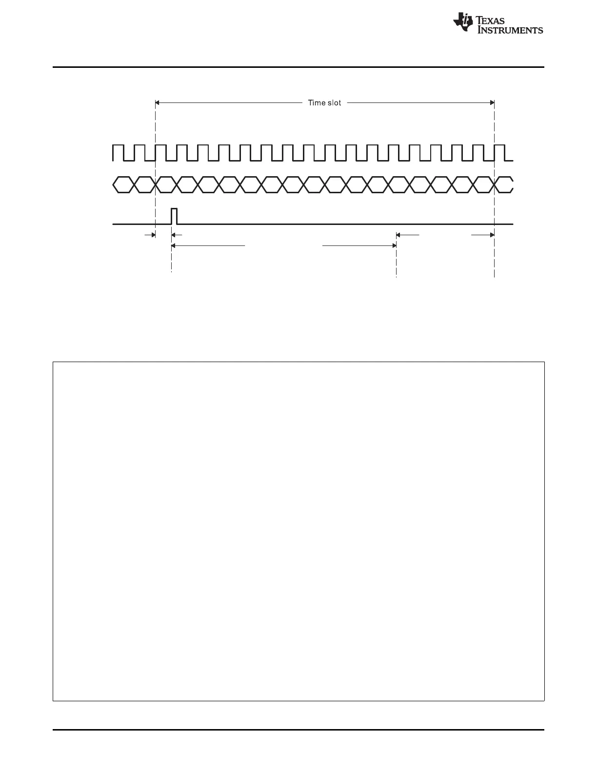
ACLKX
AXR
AXEVT
N ACLKX cycles (N=number of bits in slot)
AXEVT
Latency
(for Word C)
Service time
Setup time
(for Word C)
3 McASP
system clocks +
4 ACLKX cycles
(to write Word C)
5 McASP
system clocks
(A)
Functional Description
www.ti.com
Figure 22-26. Processor Service Time Upon Transmit DMA Event (AXEVT)
A Refer to the device-specific data manual for the McASP system clock source. This is not the same as AUXCLK.
Example 22-1. Processor Service Time Calculation for Transmit DMA Event (AXEVT)
The following is an example to show how to calculate Processor Service Time. Assume the following setup:
• McASP transmits in I2S format at 192 kHz frame rate. Assume slot size is 32 bit.
With the above setup, we obtain the following parameters corresponding to Figure 22-26:
• Calculation of McASP system clock cycle:
– System functional clock = 26 MHz
– Therefore, McASP system clock cycle = 1/26MHz = 38.5 ns.
• Calculation of ACLKX clock cycle:
– This example has two 32-bit slots per frame, for a total of 64 bits per frame.
– ACLKX clock cycle is (1/192 kHz)/64 = 81.4 ns.
• Time Slot between AXEVT events:
– For I2S format, McASP generates two AXEVT events per 192 kHz frame.
– Therefore, Time Slot between AXEVT events is (1/192 kHz)/2 = 2604 ns.
• AXEVT Latency:
= 5 McASP system clocks
= 38.5 ns × 5 = 192.5 ns
• Setup Time
= 3 McASP system clocks + 4 ACLKX cycles
= (38.5 ns × 3) + (81.4 ns × 4)
= 441.1 ns
• Processor Service Time
= Time Slot - AXEVT Latency - Setup Time
= 2604 ns - 441.1 ns - 192.5 ns
= 1970.4 ns
3800
Multichannel Audio Serial Port (McASP) SPRUH73H–October 2011–Revised April 2013
Submit Documentation Feedback
Copyright © 2011–2013, Texas Instruments Incorporated

 Loading...


