A1 A0 B15 B14 B13 B12 B11 B10 B9 B8 B7 B6 B5 B4 B3 B2 B1 B0 C15
ACLKR
AXR
AREVT
Time slot
N ACLKR cycles (N=number of bits in slot)
AREVT
Latency
(for Word A)
5 McASP
system clocks
(A)
Service time
Setup time
(Must read Word A
before this period)
3 McASP system
clocks + 4 ACLKR
(to read Word A)
cycles
McASP latches
last bit of Word A
McASP latches
last bit of Word B
www.ti.com
Functional Description
22.3.10.1.1.2 Receive Data Ready
Similarly, the receive data ready flag RDATA bit in the RSTAT reflects the status of the RBUF register.
The RDATA flag is set when data is transferred from the XRSR[n] shift registers to the XRBUF[n] buffers,
indicating that the RBUF contains received data and is ready to have the processor read the data. This
flag is cleared when the RDATA bit is written with a 1, or when all the serializers configured as receivers
are read.
Whenever RDATA is set, an DMA event AREVT is automatically generated to notify the DMA of the RBUF
ready status. An interrupt ARINT is also generated if RDATA interrupt is enabled in the RINTCTL register
(See Section 22.3.13.3 for details).
For DMA requests, the McASP does not require RSTAT to be read between DMA events. This means that
even if RSTAT already has the RDATA flag set to 1 from a previous request, the next transfer triggers
another DMA request.
Since all serializers act in lockstep, only one DMA event is generated to indicate that all active receive
serializers are ready to receive new data.
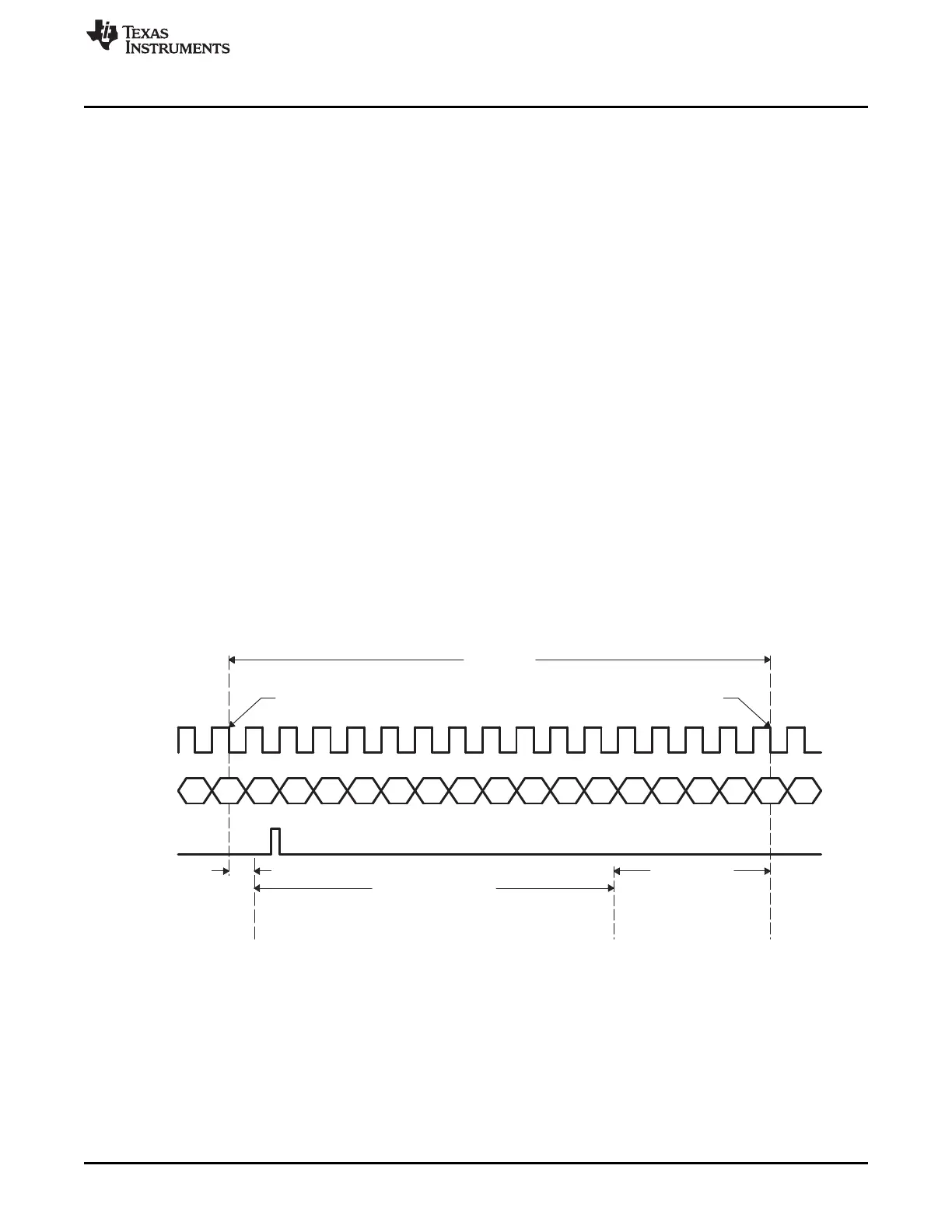
Figure 22-27 shows the timing details of when AREVT is generated at the McASP boundary. In this
example, as soon as the last bit (bit A0) of Word A is received, the McASP sets the RDATA flag and
generates an AREVT event. However, it takes up to 5 McASP system clocks (AREVT Latency) before
AREVT is active at the McASP boundary. Upon AREVT, the processor can begin servicing the McASP by
reading Word A from the RBUF (Processor Service Time). The processor must read Word A from the
XBUF no later than the setup time required by the McASP (Setup Time).
The maximum Processor Service Time (Figure 22-27) can be calculated as:
Processor Service Time = Time Slot - AREVT Latency - Setup Time
The Processor Service Time calculation for receive is similar to the calculation for transmit. See
Example 22-1 for Processor Service Time calculation using transmit as an example.
Figure 22-27. Processor Service Time Upon Receive DMA Event (AREVT)
A The device uses SYSCLK2 as the McASP system clock source.
3801
SPRUH73H–October 2011–Revised April 2013 Multichannel Audio Serial Port (McASP)
Submit Documentation Feedback
Copyright © 2011–2013, Texas Instruments Incorporated

 Loading...


