Functional Description
www.ti.com
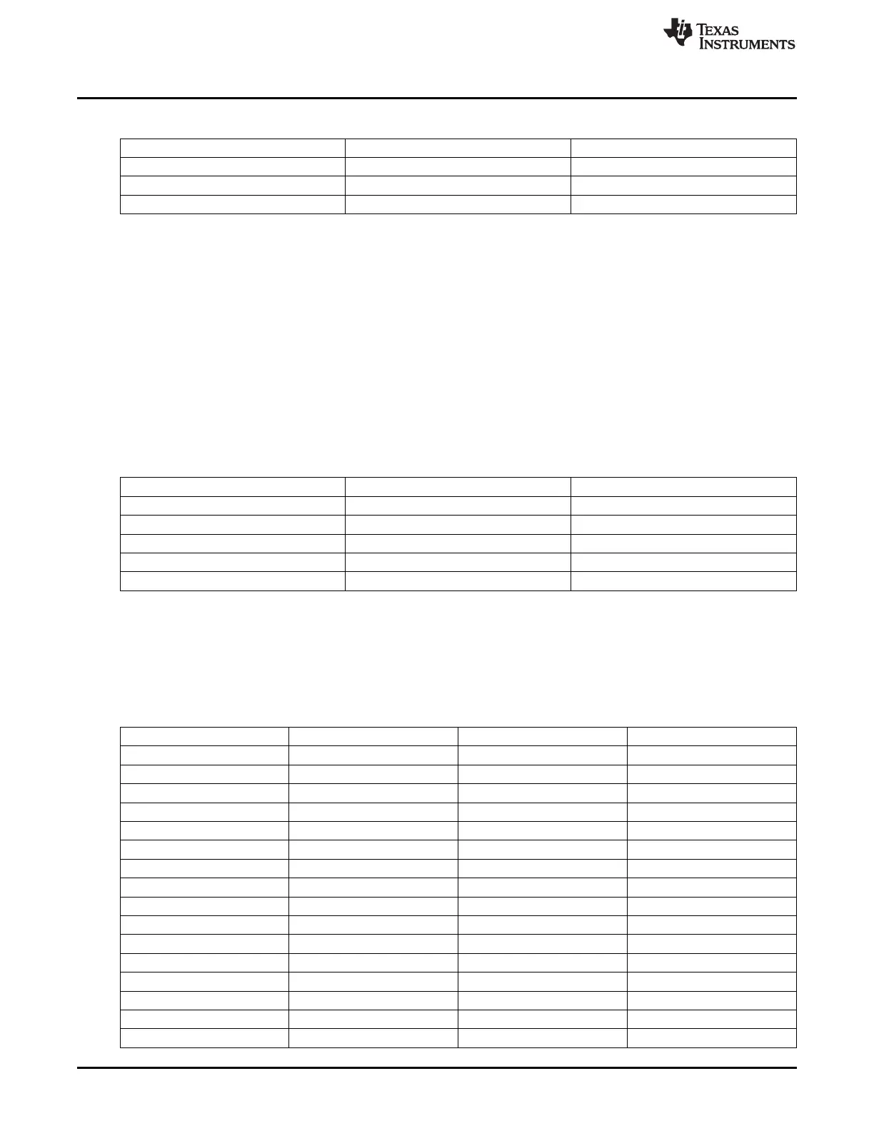
Table 26-12. NAND Timings Parameters (continued)
Parameter Description Value [clock cycles]
t
rddata
CE low to data latch time 21
t
OEoff
CE low to OE high time 24
t
WEoff
CE low to WE high time 22
Figure 26-11 and Table 26-12 describes the timings configured for NAND device access. The one clock
cycle is 20 ns, which correspond to 50-MHz frequency.
Device Detection and Parameters
The ROM Code first performs an initial wait for device auto initialization (with 250ms timeout) with polling
of the ready information. Then, it needs to identify the NAND type connected to the GPMC interface. The
GPMC is initialized using 8 bits, asynchronous mode. The NAND device is reset (command FFh) and its
status is polled until ready for operation (with 200ms timeout). The ONFI Read ID (command 90h /
address 20h) is sent to the NAND device. If it replies with the ONFI signature (4 bytes) then a Read
parameters page (command ECh) is sent. If the parameters page does not have the ONFI signature, then
the ONFI identification fails. If the ONFI identification passes, the information shown in Table 26-13 is then
extracted: page size, spare area size, number of pages per block, and the addressing mode. The
remaining data bytes from the parameters page stream are simply ignored.
Table 26-13. ONFI Parameters Page Description
Offset Description Size (bytes)
6 Features supported 2
80 Number of data bytes per page 4
84 Number of spare bytes per page 2
92 Number of pages per block 4
101 Number of address cycles 1
If the ONFI Read ID command fails (it will be the case with any device not supporting ONFI) then the
device is reset again with polling for device to be ready (with 200ms timeout). Then, the standard Read ID
(command 90h / address 00h) is sent. If the Device ID (2
nd
byte of the ID byte stream) is recognized as
being a supported device then the device parameters are extracted from an internal ROM Code table. The
list of supported devices is shown in Table 26-14.
Table 26-14. Supported NAND Devices
Capacity Device ID Bus Width Page size
512 Mb F0 x8 2048
512 Mb C0 x16 2048
512 Mb A0 x8 2048
512 Mb B0 x16 2048
512 Mb F2 x8 2048
512 Mb C2 x16 2048
512 Mb A2 x8 2048
512 Mb B2 x16 2048
1 Gb F1 x8 2048
1 Gb C1 x16 2048
1 Gb A1 x8 2048
1 Gb B1 x16 2048
2 Gb DA x8 2048
2 Gb CA x16 2048
2 Gb AA x8 2048
2 Gb BA x16 2048
4120
Initialization SPRUH73H–October 2011–Revised April 2013
Submit Documentation Feedback
Copyright © 2011–2013, Texas Instruments Incorporated

 Loading...


