Power, Reset, and Clock Management
www.ti.com
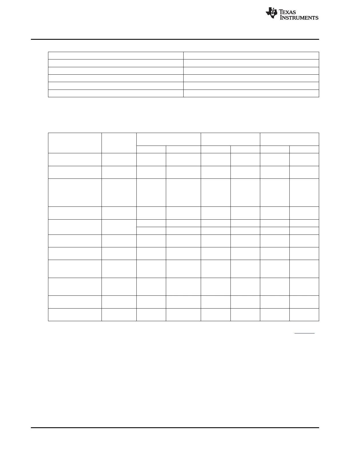
Table 8-21. PLL and Clock Frequences
Mux Select Register Bit Section 9.2.4.4
A PRCM.CLKSEL_GFX_FCLK[1]
B PRCM.CLKSEL_GFX_FCLK[0]
C PRCM.CLKSEL_PRU-ICSS_OCP_CLK[0]
D PRCM.CM_CPTS_RFT_CLKSEL[0]
E TEST.CDR (via P1500)
Table 8-22 gives the typical PLL and clock frequencies. The HSDIVIDER is used to generate three divided
clocks M4, M5 & M6. M4 & M5 are nominally 200 & 250 MHz, respectively.
Table 8-22. Core PLL Typical Frequencies (MHz)
Power-On-Reset /
OPP100 OPP50
(1) (2)
HSDIVIDER Bypass
CLOCK Source
DIV Freq DIV Value Freq (MHz) DIV Value Freq (MHz)
CLKDCOLDO (PLL
APLLS - - - 2000 - 100
Lock frequency)
HSDIVIDER-
CORE_CLKOUTM4 - Mstr Xtal 10 200 1 100
M4
L3F_CLK, L4F_CLK,
PRU-ICSS IEP CLK,
CORE_CLKO
DebugSS clka, - Mstr Xtal - 200 - 100
UTM4
SGX.MEMCLK,
SGX.SYSCLK
CORE_CLKO
L4_PER, L4_WKUP 2 Mstr Xtal / 2 2 100 2 50
UTM4
1 Mstr Xtal 1 200 1 100
CORE_CLKO
SGX CORECLK
UTM4
2 100 2 50
HSDIVIDER-
CORE_CLKOUTM5 - Mstr Xtal 8 250 1 100
M5
MHZ_250_CLK (Gigabit CORE_CLKO
- NA - 250 - NA
RGMII) UTM5
MHZ_125_CLK
CORE_CLKO
(Ethernet Switch Bus 2 Mstr Xtal / 2 2 125 2 50
UTM5
Clk)
MHZ_50_CLK (100
CORE_CLKO
mbps RGMII or 10/100 5 Mstr Xtal / 5 5 50 2 50
UTM5
RMII)
MHZ_5_CLK (10 mbps
MHZ_50_CLK 10 Mstr Xtal / 50 10 5 10 5
RGMII)
HSDIVIDER
CORE_CLKOUTM6 - Mstr Xtal 4 500 1 100
M6
(1)
Not all interfaces and peripheral modules are available in OPP50. For more information, see the device specific datasheet.
(2)
For limitations using OPP50, see AM335x ARM Cortex-A8 Microprocessors (MPUs) Silicon Errata (literature number SPRZ360).
The ADPLLS module supports two different bypass modes via their internal MNBypass mode and their
external Low Power Idle bypass mode. The PLLs are in the MNBypass mode after power-on reset and
can be configured by software to enter Low Power Idle bypass mode for power-down.
When the Core PLL is configured in bypass mode, the HSDIVIDER enters bypass mode and the
CLKINBYPASS input is driven on the M4, M5, and M6 outputs. CLKINBYPASS defaults to the master
oscillator input (typically 24 MHz).
526
Power, Reset, and Clock Management (PRCM) SPRUH73H–October 2011–Revised April 2013
Submit Documentation Feedback
Copyright © 2011–2013, Texas Instruments Incorporated

 Loading...


