TBCNT
EPWMxA
EPWMxB
TBPRD
(value)
CA
CA
CA
CA
CBCB
CB
CB
CB
Enhanced PWM (ePWM) Module
www.ti.com
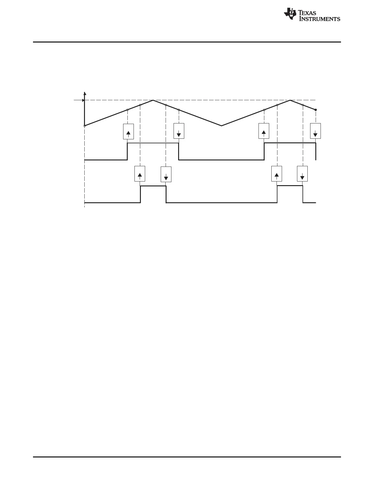
Table 15-27 and Table 15-28 contains initialization and runtime register configurations for the waveforms
in Figure 15-30. Use the code in Example 15-1 to define the headers.
Figure 15-30. Up-Down-Count, Dual Edge Symmetric Waveform, With Independent Modulation on
EPWMxA and EPWMxB — Active Low
(1) PWM period = 2 x TBPRD × T
TBCLK
(2) Duty modulation for EPWMxA is set by CMPA, and is active low (that is, the low time duty is proportional to
CMPA).
(3) Duty modulation for EPWMxB is set by CMPB and is active low (that is, the low time duty is proportional to
CMPB).
(4) Outputs EPWMxA and EPWMxB can drive independent power switches
1528
Pulse-Width Modulation Subsystem (PWMSS) SPRUH73H–October 2011–Revised April 2013
Submit Documentation Feedback
Copyright © 2011–2013, Texas Instruments Incorporated
 Loading...


