GPMC_FCLK
GPMC_CLK
nBE1/nBE0
nCS
WAIT
nADV
nOE
DIR
A 0 A 1 A 2 A 3 A 4
D 0 D 1 D 2 D 3 D 3
OUT
IN
OUT
CSONTIME
ADVONTIME
OEONTIME
RDACCESSTIME
PAGEBURSTACCESSTIME
OEOFFTIME1
CSRDOFFTIME1
ADVRDOFFTIME0
CSRDOFFTIME0
RDCYCLETIME0
RDCYCLETIME1
OEOFFTIME0
PAGEBURSTACCESSTIME
A[27:1]
D[15:0]
www.ti.com
GPMC
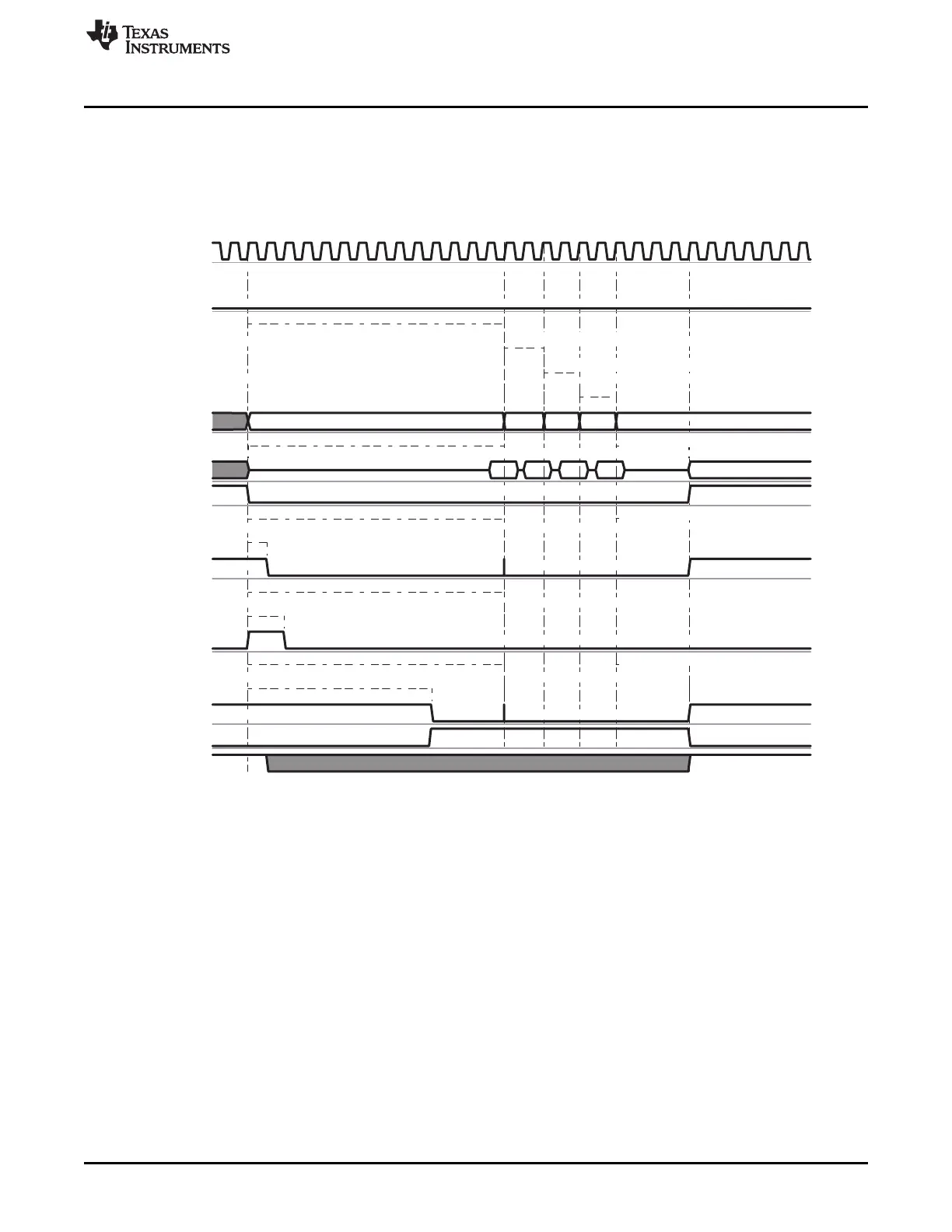
7.1.3.3.10.3.3 Asynchronous Multiple (Page Mode) Read Operation on a Nonmultiplexed Device
Figure 7-26 shows an asynchronous multiple read operation on a Nonmultiplexed Device, in which two
word32 host read accesses to the GPMC are split into one multiple (page mode of 4 word16) read access
to the attached device.
Figure 7-26. Asynchronous Multiple (Page Mode) Read
The WAIT signal is active low.
CSn, ADVn, OEn and DIR signals are controlled in the same way as address/data multiplexed accesses,
see Section 7.1.3.3.10.1.1.2.
When RDACCESSTIME completes, control-signal timings are frozen during the multiple data transactions,
corresponding to PAGEBURSTACCESSTIME multiplied by the number of remaining data transactions.
Read data is latched at GPMC_CONFIG5_i[20-16] RDACCESSTIME completion time. The end of the
access is defined by the GPMC_CONFIG5_i[4-0] RDCYCLETIME parameter.
During consecutive accesses, the GPMC increments the address after each data read completes.
Delay between successive read data in the page is controlled by the GPMC_CONFIG5_i[27-24]
PAGEBURSTACCESSTIME parameter. Depending on the device page length, the GPMC can control
device page crossing during a burst request and insert initial RDACCESSTIME latency. Note that page
crossing is only possible with a new burst access, meaning a new initial access phase is initiated.
Total access time RDCYCLETIME corresponds to RDACCESSTIME plus the address hold time starting
from the CSn deassertion.
• The read cycle time is defined in the GPMC_CONFIG5_i[4-0] RDCYCLETIME field.
• In Figure 7-26, the RDCYCLETIME programmed value equals RDCYCLETIME0 (before paged
accesses) + RDCYCLETIME1 (after paged accesses).
299
SPRUH73H–October 2011–Revised April 2013 Memory Subsystem
Submit Documentation Feedback
Copyright © 2011–2013, Texas Instruments Incorporated
 Loading...


